Masonry reinforcement FAQ

Answers

1. Why should I add masonry reinforcement?

Masonry has high compressive strength and low tensile strength. Adding reinforcement enhances the structural performance and strength of the masonry by increasing its in- and out-plane capacities. This increases crack control in the structure. 
Reinforcement benefits both structural and traditional masonry. 


Back to top

2. Can I use any type of reinforcement to any type of masonry?

Any reinforcement is better than no reinforcement. However, if your masonry is to last at least a couple of decades it is important to choose a type of masonry reinforcement that is adapted to the environment in which the structure is located and the materials from which it is build.  

Bekaert offers two types of Murfor® Compact: 

  • Murfor® Compact I for use in a dry environment (MX1). 
  • Murfor® Compact E for masonry exposed to a damp environment (MX3 and MX4).


Back to top


3. How do I adjust Murfor® Compact to the width of the wall?

Murfor® Compact is available in two convenient widths that can be matched to any brick width. Contact us for more detailed information. 

Murfor® Compact I

Murfor® Compact I-50

Murfor® Compact I-50

Mesh of 7 steel cords

Murfor® Compact I-100

Murfor® Compact I-100

Mesh of 14 steel cords

Murfor® Compact E

Murfor® Compact I-35

Murfor® Compact I-35

Mesh of 7 stainless steel cords

Murfor® Compact E-70

Murfor® Compact E-70

Mesh of 14 stainless steel cords

4. How do I apply Murfor® Compact?

Apply Murfor® Compact to the blocks

Apply Murfor® Compact to the blocks

Apply a layer of mortar.

Apply a layer of mortar.

Put the blocks in place.

Put the blocks in place.

Use a minimum overlap of 500 mm.

Alternate the alignment of the overlaps

5. For what applications can I use Murfor® Compact I?

5.1 Stress concentrations

Stress concentrations around window openings can be absorbed by applying two layers of Murfor® Compact I above and below the window.

With two layers of Murfor® Compact I

Without two layers of Murfor® Compact I

5.2 Long walls

Shrinkage or expansion of materials can lead to cracks in the masonry. Murfor® Compact I allows for larger gaps between movement joints.

With Murfor® Compact I

With Murfor® Compact I

Without Murfor® Compact I

Without Murfor® Compact I

5.3 Point loads

Point loads, e.g., ball joints, are highly concentrated loads that cause tensile stress and cracks in the masonry. Using a concrete beam as support interferes with the homogeneous character of the masonry. 

Depending on the volume of the load, three to five of the underlying joints can be reinforced with Murfor® Compact I. The reinforcement ensures the even distribution of the load. It is important to check that the contact stress between the point load and the masonry is smaller than or equal to the calculated value of the compressive strength of the masonry. 

5.4 Partition walls susceptible to deformation

Partition walls on a floor plate will start to crack in different places where there is too much sagging. To prevent this, you can reinforce and isolate the wall from the support with Murfor® Compact I.

5.5 Stack bonded masonry

Murfor® Compact I guarantees stability of the masonry with and without a stack bond. For masonry with a stack bond, the bricks are placed directly above each other, meaning reinforcement is essential for wall stability. With masonry without overlaps, reinforcement is required to compensate for insufficient bending bonding.

5.6 Corner and T-connections

Murfor® Compact I reinforcement, combined with Murfor® EFC/Z wall angle elements provide the perfect corner connection. Finish corners with 140 mm wide blocks with Murfor® Compact I-100. Corners with 200 mm wide blocks should be finished with 2 x Murfor® Compact I-50.

5.7 Laterally loaded wall panels

Wind loaded walls Murfor® Compact allows longer or thinner wall partitions that can withstand high wind loads. Retaining walls Cellar walls, retaining walls or silo walls are exposed to considerable stresses from lateral loading. Murfor® Compact increases the loading capacity of the wall span between the columns.


6. For what applications can I use Murfor® Compact E?

6.1 Stress concentrations

Murfor® Compact E provides additional reinforcement in places with high stress concentration: 

  • With level differences
  • At the wall base 
  • Above window and door opening
  • Under window sills Murfor® Compact E

6.2 Long walls

Shrinkage or expansion of materials can lead to cracks in the masonry. Murfor® Compact E allows for larger gaps between movement joints. These larger distances depend on: 

  • Type and color of the facing brick
  • Type of mortar or glue
  • Type of joint 
  • Age of the bricks
  • Orientation 
  • Temperature at implementation
  • Type of obstacle

6.3 Gables

Improve the stability of gables by reinforcing a joint every 300 mm with Murfor® Compact E. If the gables are more than 8 m high it is recommended to reinforce every 200 mm with Murfor® Compact E. Always take the recommendations for long walls into account.


6.4 Differential settlements

Masonry on partly hardened soil or uneven terrain is susceptible to deformations and stresses. This is why it is recommended to reinforce the masonry.

Recommended reinforcement: 

  • Reinforce the first 5 joints and foundation with Murfor® Compact E. 
  • Reinforce masonry located higher up every 400 mm

6.5 Facade support

Prevent cracks by reinforcing one or two joints above the facade support with Murfor® Compact E.

6.6 Stack bonded masonry

Reinforce the masonry every 300 mm with Murfor® Compact E to compensate the insufficient bonding in stacked masonry.

6.7 Laterally loaded wall panels

Murfor® Compact allows longer or thinner wall partitions that can withstand high wind loads.

6.8 Masonry beam design

Masonry beams with Murfor® Compact E absorb the bending moments over windows and doors. They can be used with soldier- or stretcher course. 

Note:

  • These beams are only suitable for non-bearing masonry, using normal masonry bonding. 
  • The mortar quality requires minimal compressive strength of M5 and a minimal bond strength of 0.20 N/mm².

Soldier course

Soldier course

Stretcher course

Stretcher course

6.9 Claustra masonry

Murfor® Compact E is available in different widths and it is extremely flexible in use, which means that it is the perfect reinforcement for claustra masonry.

7. How do I anchor the masonry?

  • Create an anchor of at least 50 cm long.
  • Apply at least 15 mm of mortar below and on top of Murfor® Compact when placing it on the joint.

8. How do I place the water retaining membrane?

9. Is Murfor® Compact ETA certified?

Murfor® Compact is ETA 18/0316 certified for structural use, which allows products to achieve CE marking. The CE mark proves that the product is tested and meets the European requirements for safety, health and environmental protection. It applies to products manufactured in the European Economic Area (EEA) and products that are manufactured outside and then marketed in the EEA.


Back to top


Masonry reinforcement FAQ

  1. Which requirements are important to select the right Beki-shield® product?

    down arrow

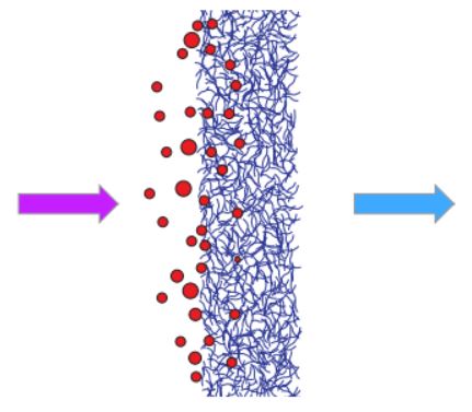
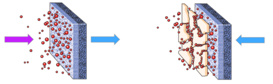
    The most important requirement is to make sure that your base polymer is compatible with the polymer coating and/or the sizing of the Beki-shield® grains. Our datasheets provide clear recommendation of which base polymers are compatible with our different types of Beki-shield® grains. The second most important consideration is the processing temperature. This should be in the range defined in the datasheets to make sure that the sizing and/or the coating dissolves correctly. (Depending on the type of product, only sizing will be present, or sizing and coating). This will ensure that all the grains open up easily and disperse well in order to create a good electrically conductive network in the plastic component.

  2. Are there any problems associated with casting SFRC against a waterproof membrane?

    down arrow

    No failures of the plastic liner due to fiber punctures have ever been identified. the abrasion from sharp aggregates during placement of the concrete poses just as big of a threat to the liner as do the steel fibers. After placement the fibers tend to move around and re-orient themselves during vibration which relieves any pressure of an individual fiber on the liner created during placement. Many projects using SFRC are constructed with cast-in-place and sprayed shotcrete directly in contact with waterproof membranes.

  3. Are there any safety hazards for finishers?

    down arrow

    No, with good jobsite safety practices in place steel fibers shall not impose any safety concerns. Please refer to our safety data sheets for further information.

  4. Can Bekipor® filter media be used for in-depth filtration and surface filtration?

    down arrow

    Bekaert’s metal fiber filtration media are suitable for both in-depth filtration and surface filtration. Here’s a short explanation of the main differences between these two types of filtration.

    In-depth filtration

    This is when the contaminants or particles that have to be removed from the flow are captured within the structure of the filter medium. In other words, the particles penetrate the medium and get captured inside.

    An in-depth filter has a 3D-structure and mostly consists of multiple layers. For the multiple layer media, the coarser fiber layers are placed at the flow-in side. Coarser particles are stopped by the coarser layer. Only small particles are held in the fine layer. This prevents premature blocking of the medium and increases the dirt holding capacity and on-stream lifetime.

    In-depth filtration is mainly used for the filtration of liquids. A typical example is the filtration of polymers.

    Since the contaminants penetrate the filter medium, off-line cleaning will be required in order to clean the filter.

    Surface filtration

    As its name suggests, with surface filtration the particles are stopped at the surface layer of the filter medium. The pore size will determine the size of particles that are stopped.

    In many cases, the filter medium will have a multi-layer structure, with the finer fiber layers at the upstream side of the flow. The particles will form a dense cake layer at the surface of the filter. This cake formation can increase the filtration efficiency, as finer particles are retained in the dense cake.

    In surface filtration, the cake formation will cause an increasing pressure drop across the filter. In the case of liquids, when the pressure drop becomes too high, a reverse filtrate flow can be initiated to remove the cake. This is called backwashing or back-flushing. In the case of gases, the cake is blown off the candle with a short blow of gas against the hot gas flow. This is called back-pulsing.

    Surface filtration can be applied in both liquid and gas filtration, especially for fine filtration.


  5. Can steel fiber reinforced concrete be pumped?

    down arrow

    Yes, but expect a 0.4” to 1.2” slump loss through the hose depending on the steel fiber dose rate, ambient temperatures and hose length. A midrange water reducing agent (MrWr) is commonly used to enhance workability and ease of flow through pump lines. High-range water reducers (HrWr) may be required in some cases. Typically, a 4” diameter hose is required.

  6. Can steel fibers be added at the ready mix plant?

    down arrow

    Yes. Introduce steel fibers after all other ingredients are already in the truck. Set the truck mixer on charging speed and add the fibers slowly into the mixer. Mix for about 5 minutes at charging speed.
    The steel fibers can also be added to the aggregate batch belt, if there is safe access.

  7. Can steel fibers be added on site?

    down arrow

    Yes, also adding fibers on site to the truck mixer is feasible. Gradually dose fibers in the mix, this is typically done via a conveyor belt.

  8. Can steel fibers be added to any mix?

    down arrow

    Steel fibers can be used in concrete, mortar and grout. Generally harsh mixtures, containing very few amount of fines and/or an unsteady sieve curve at a higher fiber volume can create mixing and dispersion problems. Simply mixing steel fibers into any concrete will most probably not utilize all the positive effects fibers can provide to concrete. Depending on the type and amount of fibers adjustments to the concrete mix may need to be made.
    For example:

    • Increasing the content of fines
    • Adjusting the grading curve
    • Adjusting the amount of plasticizer

    For concrete strength up to an actual strength of around 8000 psi typical fibers with normal strength wire are sufficient (majority of applications). For higher concrete strength´s than middle strength or high strength, fibers can be required to avoid a brittle behaviour. If special cements, aggregates or admixtures are used (seldom the case), a preliminary mix/pump test is recommended.

  9. Do steel fibers affect the concrete slump?

    down arrow

    Yes, the addition of steel fibers at typical dosage rates of 25 to 65 lb/yd3 will reduce the apparent slump by 1” to 3”. However, this does not necessarily equal a reduction in workability. Use of vibratory consolidation, restores the workability to the SFRC.

  10. Does the Beki-shield® product increase the strength of the final product?

    down arrow

    The Beki-shield® product does slightly increase the strength of the final product. If you are looking for solutions specifically to increase the strength of plastics and composites through the use of stainless steel fibers, check out our detailed information on composite reinforcement with stainless steel fibers.

  11. Does this EPD certificate comply with local/national sustainability certifications?

    down arrow

    Yes, this EPD certificate follows the EN15804, followed by most other national certification agencies.

    In those countries where regulations differ from EPD standards, we will involve the relevant parties to assess the differences and decide whether additional certification is required.

  12. For cast-in-place SFRC when is internal vibration used and when is form vibration used?

    down arrow

    For cast insitu, internal vibration is the most used option to consolidate the concrete. Form vibration is generally used in the precast industry.

    When steel fiber concrete is cast into form work a small amount of vibration of the forms helps keep the fibers from touching the forms and thereby from being visible when the forms are removed. For example, during casting of steel fiber reinforced precast structures, the forms are vibrated to consolidate the concrete. This action results in an almost fiber free surface of the structures. So allowing a short period of form vibration in the all cast-in-place structures, in addition to internal vibration where possible, will provide the best finished surface.

  13. How can I get support for the selection of the right Beki-shield® product and a quote?

    down arrow

    Please contact our headquarters. We will put you in touch with the relevant R&D and technical application engineers who can help you select the right material or can design the right product specifically for your needs. Also in the other regions outside Europe we have highly skilled technical and commercial people available who can respond to your specific requests.

  14. How can I quantify the differences between various steel fibers?

    down arrow

    The post crack strength of steel fiber concrete is a material property which is commonly used to differentiate fiber performance. This will typically be determined with a bending test and is often referred to as the residual flexural strength (see below). For the same concrete composition, steel fiber performance is a function of fiber length, diameter, aspect ratio, anchorage and tensile strength. A fiber dosage alone has no performance related value at all. AStM international has two flexural testing procedures for fiber reinforced concrete. The two testing procedures are AStM c1399 Standard test Method for obtaining Average residual-Strength of Fiber-reinforced concrete and AStM c1609 Standard test Method for Flexural Performance of Fiber-reinforced concrete. Bekaert propose the use of AStM c1609. AStM c1399 can lead to inflated post crack flexural strengths due to favorable fiber orientation and the use of a steel plate to control the first crack’s energy release.

  15. How can you successfully use the Beki-shield® product?

    down arrow

    The most important aspect for successful use of the Beki-shield® product is to make sure that the amount of shear is sufficient to open the pellets but not too much to break up the fibers in the  conductive network. The Beki-shield® grains, which contain stainless steel fibers, provide electrical conductivity by making a conductive network in the plastic part. If the shear forces are excessive, the fiber length is reduced too much, and it will become more difficult for the fibers to form the network. If this happens, the electrical conductivity of the final part will be reduced. On the other hand, it is important to have a certain amount of shear present during the processing, as shown in the figure below. Insufficient shear leads to granulates, which will also make it difficult for the stainless steel fibers to form a conductive network.

    Relation of SE (= Shielding Effectiveness) vs SHEAR FORCES

    Our datasheets provide clear recommendations on the parameters that influence the shear during the compounding and injection molding processes. Bekaert’s experienced application engineers are also available to help you fine-tune the settings of your processing to make sure you reach the best conductivity possible with our Beki-shield® products.

  16. How does the Beki-shield® product affect the mechanical properties of the end product?

    down arrow

    Due to the very low load levels, which are needed to reach the right levels of electrical conductivity for electromagnetic interference (EMI) shielding or electrostatic discharge (ESD) protection, the Beki-shield® products have an insignificant impact on the mechanical properties of the end product. This is clear from the figure below which compares carbon fiber (CF) with the stainless steel fibers of the Beki-shield® product. You can see that the reduction in impact strength to reach the same level of EMI shielding is significantly less with the stainless steel fibers of the Beki-shield® product than with the CF product. Do not hesitate to contact us for more information on the test below or other mechanical properties.


  17. How much mixing time is required when adding steel fibers to a ready mix truck?

    down arrow

    Bekaert recommends continuing mixing at the highest drum speed for about 4 to 5 minutes after all steel fibers are added to the truck.

  18. How will steel fibers affect my concrete mix design?

    down arrow

    Steel fiber mix designs are similar to those commonly used for plain concrete mixes. Recommended aggregate gradations and mix proportions are provided in local standards. Using the largest practical top size aggregate and a well-graded combined aggregate blend as opposed to a gap-graded blend can minimize shrinkage. Steel fibers may cause a reduction in slump due to their stiffness. This does not necessarily equal a reduction in workability. Depending on ambient temperatures and placement method, mid-range water reducers are commonly used to enhance workability for mixes with more than 30 to 40 pounds per cubic yards of steel fibers.

  19. Is my processing equipment damaged by the stainless steel fibers in the Beki-shield® product?

    down arrow

    Along with the Fraunhofer Institute in Germany, Bekaert has conducted extensive research on the impact of stainless steel fibers on the wear of processing equipment. Tests were performed with four different polymer compounds containing four different types of fillers. In the DKI platelet test we analyzed the wear on test plates that consisted of steel typically used to manufacture cylinders or barrels of extruders. The measurements of the weight loss of the test plates and visualization of the wear pattern by chromatic confocal microscopy gave a clear indication of the impact on the wear by the different filler materials. The table below shows that the stainless steel fibers of the Beki-shield® product make no difference to wear compared to the results obtained with the pure polymer without filler materials. This is mainly due to the fact that the stainless steel fibers are very ductile, and only low amounts need to be added to reach the desired levels of conductivity. Do not hesitate to contact us for more information or to receive the complete test report.


  20. Is the concrete electrically conductive and does this lead to a risk of electrical shock?

    down arrow

    Typical steel fiber reinforced concrete contains less than 0.5% vol. Steel fibers and hardly more than 0.75% vol. Those fibers are discontinuous and not connected to each other. Tests only show a slight decrease in electrical resistivity due to the addition of steel fibers. However, the resistance to current flow is still substantial. Effects from moisture content and aggregate composition are much more dominant than the addition of steel fibers.

  21. Is working with traditional concrete reinforcement cheaper than working with steel fiber?

    down arrow

    Steel fiber concrete compresses the construction schedule, allows for alternative construction methods or design solutions and increases durability. When a project is delivered quicker with fewer efforts and labor, the higher costs of the steel fibers are overcompensated by the savings.

    In certain applications the volume weight of steelfibers is lower as the rebar for a similar reinforcing effect. For those applications the cost/reinforcement is lower for steelfibers.

  22. What are Bekaert's sustainability ambitions?

    down arrow

    Click here to learn more.

  23. What is EMI shielding and how can the Beki-shield® product increase shielding effectiveness?

    down arrow

    Electromagnetic Interference (EMI) is caused by electromagnetic waves, which can originate from all sorts of different man-made or natural sources (e.g. lightning, power converters, radio antennas, wireless connection, computer clocks, ….). These electromagnetic waves can disturb the proper functioning of sensitive electronic equipment. In some cases, this interference is unacceptable and the correct functioning of your equipment needs to be guaranteed (e.g. anti-collision sensors in a car, EMG equipment, ….). In these cases it is required that a barrier is created in the housing (conductive plastic) which can act as a shield to prevent electromagnetic waves from leaving their source or entering the equipment which needs to be protected.

    The barrier functions on the principle of the Faraday cage. As shown in the figure below, the Faraday cage will ensure that the power of the incoming wave is reflected and absorbed. By doing so it will reduce the power of the outgoing wave. The shielding effectiveness (SE) of this boundary is a clear indication of how well the boundary can reduce the incoming power of the electromagnetic wave. The higher the SE, the better the boundary will prevent electromagnetic waves from leaving their source or from entering the electrical device.

    Shielding effectiveness is determined by the frequency, the distance from the source, the type of electromagnetic field (near or far field), the magnetic permeability, the electrical conductivity and the thickness of the boundary. The stainless steel fibers of the Beki-shield® product will make sure that the plastic housing of your electronic equipment reaches extremely high levels of electrical conductivity and thus high levels of shielding effectiveness at very low load levels. This is shown in the figure below, which compares nickel-coated carbon fiber, carbon fiber and Beki-shield®. Our white paper goes into more detail on the exact functioning of EMI shielding and how Beki-shield® provides the highest shielding effectiveness possible.


  24. What is ESD protection and how can the Beki-shield® product improve it?

    down arrow

    Electrostatic discharge (ESD) is a common phenomenon in daily life, usually experienced as a small electric shock after touching a metal item that is electrically isolated from the ground. ESD is caused by the difference in electrical charge between an electrically loaded item and the ground. In most cases this phenomenon is rather harmless, but in some situations it can cause damage to electronic equipment, or lead to dangerous situations in explosion-proof environments.

    To prevent electrostatic charges from building up and releasing as sparks, the metal fibers from the Beki-shield® product, when added to a plastic component, create a conductive matrix. In this way the electrical charges can be reduced by “bleeding off” over the grounded part, or from contact with the air. The Beki-shield® product performs an additional valuable role by allowing metal parts to be replaced with lightweight plastic parts. Furthermore, it gives you the option to color your final product while maintaining the required electrical conductivity. Our white paper provides more information on ESD protection and how the Beki-shield® product can improve it.

  25. What is an EPD and why is Bekaert now starting to use it?

    down arrow

    An Environmental Product Declaration (EPD) is an independently verified and registered report that communicates transparent and comparable information about the lifecycle environmental impact of products in a credible way. An EPD is compliant with the ISO 14025 standard.          

    Bekaert wants to help customers improve the sustainability of their construction/building assets and has therefore worked with ITB to obtain an EPD certification for its Dramix® portfolio, manufactured in Petrovice (Czech Republic), our largest manufacturing plant, as well as in Lonand (India) and Karawang (Indonesia).

    Other plants will follow the same process in the near future, with our goal to have our full portfolio covered by end of 2022.

    In addition, we are working with  One Click LCA to enable customers to efficiently compare Dramix® based solutions for the sustainability advantages they bring on construction/building assets and processes. It gives a base for comparison with alternative (mainly traditional) reinforcement solutions and it reinforces our commitment to incorporate lifecycle assessment into our sustainability ambition.

  26. What is meant by residual strength?

    down arrow

    The residual flexural strength is equal to the post crack flexural strength of steel fiber concrete corresponding to a certain deflection in a beam bending test. It is a value from testing which has been introduced for the design of steel fiber concrete.

  27. What is steel fiber reinforced concrete? (SFRC)

    down arrow

    Steel fiber reinforced concrete is an alternative to traditional reinforced concrete for certain application areas. Steel fibers are a discontinous, 3-dimensionally orientated, isotropic reinforcement, once they are mixed into the concrete. Steel fibers bridge the crack at very small crack openings, transfer stresses and develop post crack strength in the concrete.

    A variety of fiber types (material, shape, size...) are available, their effect in concrete varies. Therefore steel fiber reinforced concrete shall never be simplified as a “concrete with steel fibers”. Steel fibers may be divided into five groups:

    • Type I - cold-drawn wire
    • Type II - cut sheet
    • Type III - melt-extracted
    • Type IV - shaved cold drawn wire
    • Type V - milled from blocks

    The vast majority belongs to group I. the common and most performing anchorage type is the “hooked end”. For the same type of fiber, length/diameter and tensile strength have the biggest influence on fiber performance. The higher the l/d ratio, the better the performance of the steel fiber reinforced concrete.

  28. What is the benefit of using steel fibers over synthetic macro fibers?

    down arrow

    Mechanically anchored steel fibers have been proven as reinforcement, even for structural application. Steel fibers are made from a material with well known engineering properties; e modulus, Poisson’s ratio, tensile strength and creep. The e-modulus of steel is greater than that of concrete. Thus, the steel fibers pick up the stresses quickly and affect the cracking process immediately. The long term load carrying capacity of the steel fiber reinforced concrete is significant. Steel fibers have a material specification of AStM A820. Macro synthetic fibers come in a large variety and have very different material properties. Macro synthetic fibers do not have a material specification in AStM. All macro synthetic fibers do have an e-modulus lower then that of concrete and relatively low tensile strengths. Thus, macro synthetic fibers need a certain crack width to occur prior to being able to engage in the concrete and then only moderate post crack strength values can be achieved. Macro synthetic fibers are also subject to creep which makes the long term loading capacity of the fiber lower or non existent. The rate of creep can be increased with increased ambient temperatures.

    There are at least four factors to review when considering reinforcement; Modulus of elasticity, Poisson’s ratio, tensile strength and creep..

  29. What is the benefit of using steel fibers over synthetic micro fibers?

    down arrow

    Steel fibers are not a replacement of synthetic micro fibers and vice versa. Both fiber types provide very different properties to concrete so that the applications fields do not overlap. Rather than a substitute, both fiber types may be used complementary. While steel fibers offer post crack strength and thus act as reinforcement, synthetic micro fibers reduce cracking due to plastic shrinkage and improve the fire resistance of concrete. They do not provide any reinforcing effect.

  30. What is the diameter range of metal fibers?

    down arrow

    The equivalent diameters of metal fibers range from 1 to 100 µm. Standard equivalent diameters are 1.5, 2, 4, 6.5, 8, 12, 22, 30 and 40 µm.

    A micron, officially called micrometer (µm), is one millionth of a meter. This is one thousandth of a millimeter. A piece of paper is usually about 100 µm thick, a human hair about 70 µm.


  31. What is the difference between absolute filter rating and nominal filter rating?

    down arrow

    Absolute filter rating

    The size of the largest pore in a filter is used as a reference to measure the performance of a filter medium. The size of the largest pore in a filter can be determined using the absolute pore size test.

    The absolute filter rating (a) is the diameter of the largest hard spherical particle that will pass through the filter element under constant flow.

    The definition of the absolute filter rating implies that 100% of the particles larger than a µm will be retained by the filter. Smaller particles are able to pass the filter, but a certain percentage of them will also be retained. The following efficiency graph illustrates this:

    Nominal filter rating

    The nominal filter rating is an arbitrary value, indicating a particulate size range; the filter manufacturer claims the filter removes some percentage of this size range. The nominal filter rating is defined differently by different manufacturers and is therefore ambiguous. Nominal ratings vary from manufacturer to manufacturer and cannot be used to compare filters. In case of nominal filtration, nominal filter rating refers to the filtration efficiency after cake formation.


    Comparison

    To compare both the absolute and nominal filter rating, their graphs are compared below. The first graph is one of a filter with an absolute filter rating of 10 µm; it is compared to a graph of a filter with a nominal filter rating of 10 µm at 98%. In this case, the absolute filter rating of the second filter is about 14 µm and the nominal filter rating of the first filter is about 9 µm.


  32. What is the difference between filtration and separation?

    down arrow

    Filtration is basically a process to separate solids from a liquid or gas stream with a porous substrate (medium). 

    Separation is the process of converting a mixture or solution of chemical substances into two or more distinct product mixtures. Examples include separating two liquids of an emulsion (water in fuel) or removing liquid mist from a gas.

  33. What load % is needed to reach the right levels of shielding effectiveness or ESD protection?

    down arrow

    With the stainless steel fibers from the Beki-shield® product you can already reach very high levels of conductivity at extremely low load levels. The table below indicates the EMI shielding effectiveness and ESD protection values possible with the Beki-shield product. The most important aspect to make sure you reach these values is to limit the shear forces on the stainless steel fibers of the Beki-shield® products. Excessive shear forces will reduce the length of the fibers too much, impairing their ability to form the network, and consequently reducing the electrical conductivity of the final part.

    Volume %
    fibers
    Weight %
    fibers (*)
    Bulk resistivity
    (Ohm.cm)
    Performance (**)
     0.25 - 0.50  4   < 10²   ESD protection
     1  8  0.5 - 2  30 - 50 dB EMI shielding
     1.5  11  0.1 - 0.5  50 - 60 dB EMI shielding
     > 1.5  >11  < 0.1  > 60 dB EMI shielding

    (*) resin density: ± 1 g/cm³ - stainless steel fiber density: ± 8 g/cm³
    (**) 30-1000 MHz shielding range

    Our datasheets provide clear recommendations of the parameters that influence the shear during the compounding and injection molding processes. Bekaert’s application engineers are also available to help you fine-tune the settings of your processing so that you reach the best conductivity possible with our Beki-shield® products.

  34. When will EPDs be available for products from other Bekaert plants?

    down arrow

    We currently have an EPD for Dramix® manufactured in Petrovice (Czech Republic), Lonand (India) and Karawang (Indonesia). This means that today, 80% of Dramix® steel fibers are manufactured at an EPD certified plant. We also have obtained an EPD for Mesh Track®.

    Next up are our plants in Wilkes Barre (Pennsylvania, US), Izmit (Turkey) and Shanghai (China), after which all of our Dramix® plants will be fully EPD certified.

    If you would like to be informed of our EPD releases and receive these documents as soon as they are available please let your Bekaert sales manager know.

  35. Which aggregate size is best for steel fiber reinforced concrete?

    down arrow

    According to the Bekaert guidelines, the maximum aggregate size should be limited to 2x the fiber length in order to obtain optimal performance. When coarser aggregates are used, we advise to conduct preliminary field trials in addition to SFRC performance tests.

  36. Why are some EPD's based on data from 2019 and others from 2021?

    down arrow

    The pandemic led to (partial) shutdowns of plants, which does not accurately portray what a normal production is usually like. As such, EPD calculations based on lifecycle data from that year would have been inaccurate. Further, some of the product lifecycle data is calculated by external agencies which only base their calculations on an entire calendar year. Therefore, the EPD's we kicked off mid 2021 or prior are based on data from 2019, and recent ones are based on data from 2021.

  37. Why should I use the Beki-shield® product to make my plastics conductive?

    down arrow

    The Beki-shield® products consist of stainless steel fibers that provide very high levels of conductivity at very low load levels. This is particularly interesting when you need to reach high levels of electromagnetic interference (EMI) shielding or electrostatic discharge (ESD) protection at low load levels. The low load levels give you the possibility to color your end product and (in comparison with carbon black) you will have non-sloughing end products, such as castor wheels which do not leave marks on floors. Low load levels also mean that mechanical properties such as impact strength and part shrinkage are not significantly affected. The Beki-shield® product is easy and safe to use in your injection molding or compounding process and enables you to design lightweight, complex components with long-lasting conductivity. It is ideal to replace metal components that require EMI shielding properties with lightweight plastic alternatives that have high EMI shielding effectiveness.

  38. Will Bekaert be conducting product-specific EPD assessments for different Dramix® fibers such as 3D, 4D and 5D?

    down arrow

    Given the similarities in the manufacturing process, this EPD certification is a good proxy for all types of Dramix® produced at EPD certified plants.

    However to be precise, we are developing a multiplier and formula together with the ITB that allows you to calculate an adjusted GWP (global warming potential, the parameter measuring CO2 emission equivalents) score for each of our fiber types. This multiplier will uploaded on this website as soon as it is available.

  39. Will fibers stick out of the joints after cast-in-place forms are removed?

    down arrow

    Fibers can only protrude from forms where there is a joint. They can not protrude in the middle of a form. This can be minimized if the joints are caulked before concrete placement. However, it is not always possible to calk every joint. The number of protruding fibers is a function of the precision of the joints and the fiber dosage.

    Wider joints will catch more fibers than tighter joints. After the formwork is removed, the fibers can be quickly knocked down with a hand sanding block or a small angle grinder.

  40. Will steel fiber reinforced concrete wear forms or tools more than plain concrete?

    down arrow

    Not more than concrete.

  41. Will steel fibers rust?

    down arrow

    For indoor applications such as tunnels and warehouses, no. For outdoor applications such as pavements some minor rusting may occur. Experience in highways and industrial pavements indicate that while individual fibers corrode at the surface, staining of the concrete surface does not occur. Overall aesthetics and serviceability are maintained even with the presence of individual fiber corrosion. Indoor Applications-Surface fibers in typical indoor tunnels or manufacturing floor applications remain bright and shiny under normal environmental conditions.

    Outdoor Applications Without cracks-experience has shown that concrete specified with a 28-day compressive strength over 3000 psi, mixed with standard water/cement ratios, and installed with methods that provide good compaction, limit the corrosion of fibers to the surface skin of the concrete. When surface fibers corrode, there is no propagation of the corrosion more than 0.008” beneath the surface. Since the fibers are short, discontinuous, and rarely touch each other, there is no continuous path for stray or induced currents between different areas of the concrete. Outdoor Applications With cracks-laboratory and field-testing of cracked SFRC in environments containing chlorides has indicated that the cracks in concrete can lead to corrosion of the fibers passing across the crack. However, small cracks (crack widths < 0.008”) do not allow corrosion of steel fibers passing across the crack. If the cracks wider than 0.008” and are limited in depth, the consequences of this localized corrosion are not structurally significant.

  42. Will the steel fibers ball up in the mix?

    down arrow

    A properly designed concrete mix is essential for avoiding fiber balling. In order to avoid the potential for fiber balling related to fibers with a high l/d (aspect) ratio (meaning high performing fibers), glued fiber technology has been developed. Glued fiber bundles will spread the glued bundles evenly on “macro level” and during mixing the bundles separate into individual fibers. In essence the glued bundle temporarily lowers the aspect (l/d) ratio of the fibers for easy mixing. That´s how balling can effectively be avoided and a homogenously mix of high performing steel fiber reinforced concrete can be achieved.

If you can't find your answer here feel free to

get in touch